
For my final project in assembly programming class this quarter I designed and built an alarm clock. It runs on an 8051 Cygnal microprocessor and displays on a 1×16 line LCD display. My alarm clock includes, a clock that runs in 24-hour time, an alarm, a count down timer, and a stopwatch. Everything displays to the nearest second. You can set the clock, alarm, and count down timer to the nearest minute. The alarm outputs a simple beeping signal from the headphone jack.
The Problems, I mean the Hardware:

This clock runs on an Cygnal prototyping board that has an 8051 micro controller on it (The IDE is available here). The prototyping board has most of the pins from the processor output to a double row of headers on one side of the board. Professor Stirling in our engineering department had designed a board (called DL6) to interface with the Cygnal board. The DL6 has four momentary buttons, four latching buttons, a headphone jack, a bank of eight DIP switches, a whole lot of LED’s, and a breadboard to interface with most of the ports on the microprocessor. I decided to get an LCD and connect it to the processor via the breadboard on the DL6 and use the buttons on the DL6 as the inputs for the clock.
I got and LCD and went hunting to figure out how to use it. I finally found a tutorial on www.8052.com and started working on it, and it started getting . . . troublesome. The first problem I had was my DL6, and Cygnal boards would only output 3.3 volts, the LCD display needed 5 volts. After I figured that out it was no small task to get 5 volts out of my board. After much hard work, we had to remove one of the pull down resistors from the DL6 board and add a pull up resistor. This got 8 outputs (from P0) to 5 volts. The LCD has 8 data lines and 3 control lines, so ideally you need 11 outputs to run the LCD. However, you can run the LCD in 4 bit mode using only use 4 data lines, but this is a little more complicated on the software end. Since I only had 8 output lines I decided to try 4 bit. Many, many, many hours later it still wouldn’t work. Despite heroic trouble shooting on my part, and going over the example 4 bit code from 8052.com (which has many errors and does not work in any way shape or form), the LCD still wouldn’t display anything. I could only get it to clear, sometimes. Back to the drawing board, my only option was 8-bit so I needed another 3 outputs. There were extra outputs on the Cygnal board, but they weren’t on the DL6 breadboard. To get to them I soldered 3 more lines straight onto my Cygnal board, and added pull-up resistors to them. I got that working in short order (the 8052.com code for 8-bit actually works) and my project was all set up, next came the actual code.
The Software:
The code seemed like it would be very easy at first but it rapidly got longer then I thought it would be. None of it was particularly challenging but there was just a lot of it to write. Basically I have a main code loop that runs through looking for one of the latches or momentary buttons to be set and that puts you in the appropriate mode loop (i.e. set clock, stopwatch, timer etc). The clock, and various timers (chronograph and countdown timer) are kept track of with independent timers that interrupt when they overflow. If you start the countdown timer or chronograph it starts a timer that will overflow and interrupt to increment or decrement the appropriate time. And of course there is always a timer running in the background to keep track of the clock time. You can run the chronograph, timer and clock simultaneously and switch around through the different modes depending on the one you want to watch, while the rest will keep track of their respective times in the background. The alarm output (beeping) is also a timer/interrupt, which overflows and interrupts around 400 times per second in order to vary the voltage we are outputting to the headphone jack.
The latching buttons are used to go into the various set modes, except LAT0. LAT3 being set alarm, LAT2 set timer, and LAT1 set clock. LAT0 is the alarm enable disable LAT; it has to be on to enable the set alarm. If LAT0 isn’t on the set alarm will not go off but the countdown timer alarm will. When you are in the set modes it will say “set clock”, “set timer”, or “set alarm” on the right hand side of the screen to let you know what set mode you are in. MOM0 is the mode button, when you press it, it will cycle you through the three modes, clock (default), timer, and chronograph. Timer and chronograph are signified by having “timer”, and “chrono” on the right hand side of the display, respectively, the clock (default) display in blank on the right. MOM1 is the chronograph and timer start/stop button, and MOM2 is the timer/chronograph reset button. MOM2 also double as the add minute button when you are in set mode and MOM3 is the add hour button in set mode.
When the timer reaches zero, or the alarm reaches its set time (provided the alarm enable LAT0 is set) it will trigger the alarm. The alarm outputs an annoying beeping signal from the headphone jack. You can hear it significantly well with headphones, but if you want bigger speakers hooked up they have to be powered speakers. If the timer sets off the alarm it will beep for approximately 30 sec, if the set alarm goes off it will beep for approximately 1 min and 30 sec.
Overall my alarm clock has nearly all of the features you would expect in a wristwatch, or an alarm clock you would have on your nightstand. Well except for snooze, and displaying tenths or hundredths of a second for the stopwatch (to be featured in version 2).
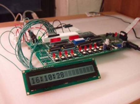
The Finished Product:
A copy of my source code can be found here. It was written with the Cygnal IDE that came with the Cygnal 8051 board.

[…] Alarm projects: Lets make a timer Timers & 8051 Timer Programming AT89C2051 Alarm Clock 8051 Alarm Clock These projects should get you started in the right direction. Reply With Quote […]